Drainage on Flat Roofs

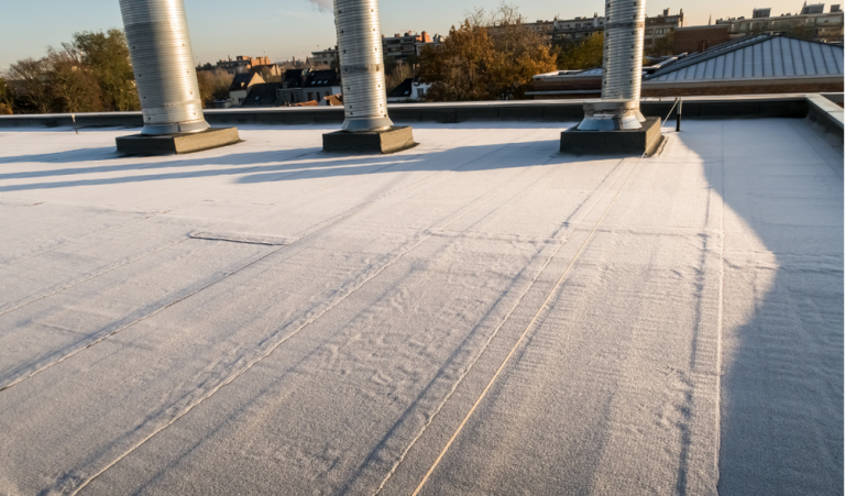
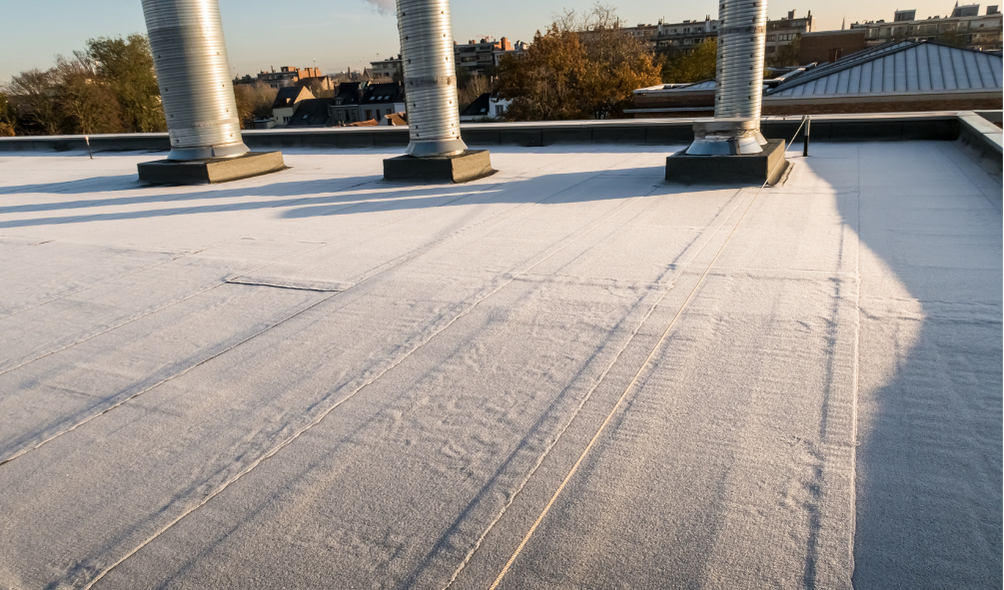
Built-up roofs, modified roofs, and single-ply roofs are often referred to as “flat roofs”, and are typically constructed with roof slopes of ¼” per foot. These roofs can be constructed with a parapet which effectively encloses the perimeter of the roof system not allowing the free flow of water over the building edge. Because of this, the Florida Building Code (FBC), mandates that both primary and secondary (emergency overflow) drainage be installed, as stated below:
[P] 1503.4 Roof drainage. Unless roofs are sloped to drain over roof edges, design and installation of roof drainage systems shall comply with Section 1503 and the Florida Building Code, Plumbing, Chapter 11.
[P] 1503.4.1 Secondary (emergency overflow) drains or scuppers. Where roof drains are required, secondary (emergency overflow) roof drains or scuppers shall be provided where the roof perimeter construction extends above the roof in such a manner that water will be entrapped if the primary drains allow buildup for any reason. The installation and sizing of secondary emergency overflow drains, leaders and conductors shall comply with Sections 1106 and 1107, as applicable, of the Florida Building Code, Plumbing, Chapter 11.
The secondary drainage requirement, as stated above, can cause some confusion for contractors, consultants, and building owners who get involved with a re-roofing project. On these types of projects, the existing roofs may not have proper drains or proper slope, and attempts are made to modify or correct these issues without a comprehensive understanding of roofing, drainage, structural, and code requirements. “Flat roofs” installed with proper slope, such as ¼” per foot, can still lack sufficient drainage to prevent the accumulation of storm water, which can result in water ponding on the roof causing increased loads. Chapter 11 of the FBC Plumbing deals with storm drainage and states that:
1101.7 Roof design. Roofs shall be designed for the maximum possible depth of water that will pond thereon as determined by the relative levels of roof deck and overflow weirs, scuppers, edges or serviceable drains in combination with the deflected structural elements. In determining the maximum possible depth of water, all primary roof drainage means shall be assumed to be blocked. The maximum possible depth of water on the roof shall include the height of the water required above the inlet of the secondary roof drainage means to achieve the required flow rate of the secondary drainage means to accommodate the design rainfall rate as required by Section 1106.
This requires that all primary roof drains be blocked when accounting for the maximum water depth. As such, Chapter 16, Section 1611 of the FBC deals with calculating design rain loads on a roof structure and states the following:
1611.1 Design rain loads. Each portion of a roof shall be designed to sustain the load of rainwater that will accumulate on it if the primary drainage system for that portion is blocked plus the uniform load caused by water that rises above the inlet of the secondary drainage system at its design flow. The design rainfall shall be based on the 100-year hourly rainfall rate indicated in Figure 1611.1 or on other rainfall rates determined from approved local weather data.
R = 5.2 (ds + dh)
For SI: R = 0.0098(ds + dh)
where:
dh = Additional depth of water on the undeflected roof above the inlet of secondary drainage system at its design flow (i.e., the hydraulic head), in inches (mm).
ds = Depth of water on the undeflected roof up to the inlet of secondary drainage system when the primary drainage system is blocked (i.e., the static head), in inches (mm).
R = Rain load on the undeflected roof, in psf (kN/m2). When the phrase “undeflected roof” is used, deflections from loads (including dead loads) shall not be considered when determining the amount of rain on the roof.
The equation shown above provides the design load, R, in pounds per square foot (PSF) and includes the “hydraulic head” and the “static head” in order to determine this design load on a roof structure. These terms, dh and ds, are determined based on the characteristics of the roof drainage system and roof slope. Depending on the age, condition, and type of construction of the existing roof structure, minimal ponding may result in an overloaded roof structure. Careful investigation of the roof structure and drainage characteristics, along with an understanding of the building code(s) prior to beginning a re-roofing project is critical to ensure the proper construction of the roof.
Please contact Burby Engineering at info@burbyengineering.com if you have roofing, structural, or building code questions.


