Burby Logo 8.1.2021
Categories
Newsletter

New Florida Condo Safety Bill

New Florida Condo Safety Bill

During a special session, Florida Lawmakers passed Senate Bill 4-D in response to the 2021 Surfside Tragedy. Now, statewide Milestone Structural Inspections will be imposed on condominium buildings. Previously, only two counties in Florida required routine inspections for existing condos.

The inspections will apply to condo buildings that are three stories or higher. The condos must be inspected at 30 years old, unless they are within three miles of the coastline. In which case, they will need to be inspected at 25 years. Re-inspections will be required every ten years. Existing condo buildings that are older than 30 years must have a Milestone Structural Inspection completed by December 31, 2024.

Under this bill, condo associations will also be required to maintain adequate financial reserves to pay for the repairs related to the structural integrity of their building. Prior to this bill, associations had the option to underfund or waive these reserves. A Structural Integrity Reserve Study to determine the amount of financial resources needed for repairs will also be required every ten years, with the initial study complete by December 31, 2024.

Licensed Engineers or Architects will inspect the buildings and determine if repairs are necessary. If a condo building does not comply or stalls with the repairs, counties will be able to condemn the building.

Request A Consultation

Categories
Newsletter

Drainage on Flat Roofs

Drainage on Flat Roofs

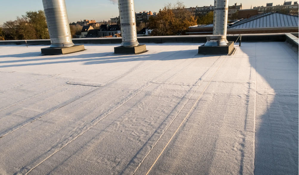
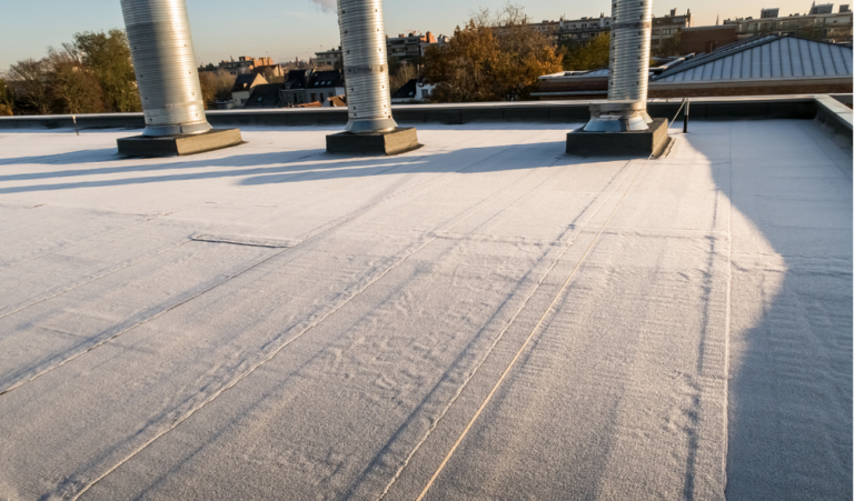
Built-up roofs, modified roofs, and single-ply roofs are often referred to as “flat roofs”, and are typically constructed with roof slopes of ¼” per foot. These roofs can be constructed with a parapet which effectively encloses the perimeter of the roof system not allowing the free flow of water over the building edge. Because of this, the Florida Building Code (FBC), mandates that both primary and secondary (emergency overflow) drainage be installed, as stated below:

[P] 1503.4 Roof drainage. Unless roofs are sloped to drain over roof edges, design and installation of roof drainage systems shall comply with Section 1503 and the Florida Building Code, Plumbing, Chapter 11.

[P] 1503.4.1 Secondary (emergency overflow) drains or scuppers. Where roof drains are required, secondary (emergency overflow) roof drains or scuppers shall be provided where the roof perimeter construction extends above the roof in such a manner that water will be entrapped if the primary drains allow buildup for any reason. The installation and sizing of secondary emergency overflow drains, leaders and conductors shall comply with Sections 1106 and 1107, as applicable, of the Florida Building Code, Plumbing, Chapter 11.

The secondary drainage requirement, as stated above, can cause some confusion for contractors, consultants, and building owners who get involved with a re-roofing project. On these types of projects, the existing roofs may not have proper drains or proper slope, and attempts are made to modify or correct these issues without a comprehensive understanding of roofing, drainage, structural, and code requirements. “Flat roofs” installed with proper slope, such as ¼” per foot, can still lack sufficient drainage to prevent the accumulation of storm water, which can result in water ponding on the roof causing increased loads. Chapter 11 of the FBC Plumbing deals with storm drainage and states that:

1101.7 Roof design. Roofs shall be designed for the maximum possible depth of water that will pond thereon as determined by the relative levels of roof deck and overflow weirs, scuppers, edges or serviceable drains in combination with the deflected structural elements. In determining the maximum possible depth of water, all primary roof drainage means shall be assumed to be blocked. The maximum possible depth of water on the roof shall include the height of the water required above the inlet of the secondary roof drainage means to achieve the required flow rate of the secondary drainage means to accommodate the design rainfall rate as required by Section 1106.

This requires that all primary roof drains be blocked when accounting for the maximum water depth.  As such, Chapter 16, Section 1611 of the FBC deals with calculating design rain loads on a roof structure and states the following:

1611.1 Design rain loads. Each portion of a roof shall be designed to sustain the load of rainwater that will accumulate on it if the primary drainage system for that portion is blocked plus the uniform load caused by water that rises above the inlet of the secondary drainage system at its design flow. The design rainfall shall be based on the 100-year hourly rainfall rate indicated in Figure 1611.1 or on other rainfall rates determined from approved local weather data.

R = 5.2 (ds + dh)

For SI: R = 0.0098(ds + dh)

where:

dh = Additional depth of water on the undeflected roof above the inlet of secondary drainage system at its design flow (i.e., the hydraulic head), in inches (mm).

ds = Depth of water on the undeflected roof up to the inlet of secondary drainage system when the primary drainage system is blocked (i.e., the static head), in inches (mm).

R = Rain load on the undeflected roof, in psf (kN/m2). When the phrase “undeflected roof” is used, deflections from loads (including dead loads) shall not be considered when determining the amount of rain on the roof.


The equation shown above provides the design load, R, in pounds per square foot (PSF) and includes the “hydraulic head” and the “static head” in order to determine this design load on a roof structure.  These terms, dh and ds, are determined based on the characteristics of the roof drainage system and roof slope.  Depending on the age, condition, and type of construction of the existing roof structure, minimal ponding may result in an overloaded roof structure. Careful investigation of the roof structure and drainage characteristics, along with an understanding of the building code(s) prior to beginning a re-roofing project is critical to ensure the proper construction of the roof.

Please contact Burby Engineering at info@burbyengineering.com if you have roofing, structural, or building code questions.

Request A Consultation

Categories
Newsletter

Shallow Foundation Requirements

Shallow Foundation Requirements

Section 1809 of the 2020 Florida Building Code, Building, 7th Edition requires shallow foundations to be placed 12-inches below the undisturbed ground surface and requires a 12-inch minimum foundation width. The relevant section states:

1809.4 Depth and width of footings. The minimum depth of footings below the undisturbed ground surface shall be 12 inches (305 mm). Where applicable, the requirements of Section 1809.5 shall also be satisfied. The minimum width of footings shall be 12 inches (305 mm).

Foundations that do not meet this building code requirement could suffer from settlement related damage. The Florida Building Code defines a “shallow foundation” as “…an individual or strip footing, a mat foundation, a slab-on-grade foundation or a similar foundation element.”

For building code questions or assistance with evaluating foundations or settlement related damage to a building or other structure, please contact Burby Engineering at info@burbyengineering.com

Request A Consultation

Categories
Newsletter

Under-Floor Ventilation Requirements

Under-Floor Ventilation Requirements

Both commercial and residential buildings whose first floors are elevated above grade have specific ventilation requirements. The Florida Building Code requires ventilation for crawl spaces that exist between the grade and the first-floor framing.  Per the Florida Building Code Section 1203.4, the vent openings shall provide cross-ventilation of the crawl space.  Moreover, the total area of vent openings shall be at least 1 square foot for every 150 square feet of crawl-space plan area. 

The code goes further to describe the types of vent materials that are permitted and then gives exceptions for when the above requirement (1:150) does not need to be met.  These exceptions include a reduction in the ratio when a Class I vapor retarder is provided and an elimination of all vent openings when continuous ventilation (i.e. fans) is provided at a given rate.

Request A Consultation

Categories
Newsletter

Proposed Multifamily Residential Building Inspection Bill

Proposed Multifamily Residential Building Inspection Bill

In response to the devastating collapse in Surfside last June, a new bill (SB 1702) has been proposed to mandate statewide “milestone inspections” for multifamily residential buildings with more than three stories. Such buildings that are within three miles of a coastline would require inspections on their 20th year and every seven years following that. Buildings outside the three-mile coastline threshold would be inspected on their 30th year and every 10 years after that.

The inspection would be conducted by a licensed Florida engineer or architect. It would be mandatory for the completed reports to be distributed to each unit owner. Under this bill, buildings cleared for occupancy prior to July 1, 1992 will have until December 31, 2024 to complete their first inspection.

This proposed legislation advanced after receiving unanimous approval from the Senate Community Affairs Committee on January 25, 2022. It will need to clear two more committees before reaching the full Senate.

Request A Consultation

Categories
Newsletter

Low-Slope Roof Drainage Systems

Low-Slope Roof Drainage Systems

To ensure the successful performance of roof coverings on low-slope roofs, the roof drainage systems must be designed and installed properly. On low-slope roofs, water is not designed to drain over the roof’s edge, unlike conventional sloped roofs.  Roof drains and scuppers should be placed at the low points of the roof and sized to convey the water at the building code required mean recurrence interval.  The flashing at drains and scuppers is a significant detail since these areas will experience excessive amounts of water by design.  Water intrusion, or even roof collapse, can occur if there are improperly located and inadequately flashed roof drains and scuppers.

Roof drains should be installed in sump areas, which are usually created by tapering the underlying insulation towards the drains. There should not be any seams of the roofing membrane located within sump areas.  To prevent water intrusion, the roof drains must be fitted with compression clamping rings.  The drain bowl should be to property attached to the drain pipe below.  In re-roofing projects, it’s important to ensure the drain bowls do not get disconnected from the drain line when the original roof is being removed.  Strainer baskets should be added to prevent blockage.  Installation of primary drainage scuppers should be level with the roof surface at the lowest elevations along parapet walls, whereas overflow scuppers should be installed not less than 2 inches and not more than 4 inches above the roof covering.  Pre-fabricated scupper inserts should be used for flashing.

These are just general recommendations for the installation of low-slope roofs.  To ensure proper installation, follow the procedures outlined in the roofing manufacturer’s published instructions.  Not only will following these details be critical for the proper installation of the product but it is also required by the building code.  Furthermore, the building code requires that testing be performed on the drainage and vent system to determine compliance with the provisions of the code.

Burby Engineering, Inc. can assist in roof design, testing, and inspections, or building code-related issues. Contact us for more info!

Request A Consultation

Categories
Newsletter

Low-Emissivity Glass Coating

Low-Emissivity Glass Coating

In an effort to reduce energy use in buildings, there have been increased energy performance requirements for newly-constructed and renovated properties.  When it comes to energy efficiency, it is critical to take a look at both windows and skylights.  Since these fenestrations are transparent, they allow the passage of heat and light, meaning that thermal losses and gains are usually greatest at these locations.

Low-emissivity, or low-e, coating is a product that was developed to help minimize the amount of UV light and heat waves that can pass through glass without compromising the amount of light transmission.  These coatings are microscopically thin, transparent metallic glass coatings that are usually installed on insulated glass (IG) units. IG units consist of at least two glass panes separated by an air gap.  The low-e coatings are typically applied to the inner surface of the interior or exterior glass pane (within the air gap), depending on the climate where the window will be in service.

For warmer climates like Florida’s, the purpose of low-e coating is to keep the heat out of the building, so the low-e coating should be installed on the exterior glass pane to reflect the solar heat back outside before it enters the insulating air gap of the window.  This will help preserve the cool air inside the building.  For colder climates, the intent of low-e coating is to minimize the heat loss through the window and maximize the solar heat provided by the sun.  In this scenario, the low-e coating should be applied to the interior glass pane to allow the heat to pass through the window and reflect the heat back inside.

Because of the transparency of low-e coatings, it can often be difficult to detect the surface on which it was applied on.  Building owners who decide to install low-e windows pay a higher price with the understanding that costs can be recouped in the long run with reduced electricity bills.  If the low-e coating is installed on the wrong glass surface, then the efficiency can be significantly reduced, or even negated.  Burby Engineering is adept in handling issues related to low-e coating installations and other window-related issues.  Contact our team to learn more!

Request A Consultation

Categories
Newsletter

Application of Wall Coatings

Application of Wall Coatings

Wall coatings are an essential part of the waterproofing system and the building envelope.  Various factors should be taken into account when selecting a wall coating, whether it is for a new project or for a restoration or re-coating application.

Preparing the surface is extremely important.  The substrate (concrete, masonry, stucco, etc.) or surface (another wall coating) should have no holes or cracks, free from dirt and debris, and dry with a manufacturer specific moisture content.

Generally, a coating is made up of four primary ingredients:  Binder, Pigment, Carrier, and Additives.  The binder is the film forming portion, and can be acrylic or silicon, among other types.  The pigment is the color.  When exposed to sunlight, bright (organic) colors tend to fade quicker.  Coatings can also be elastomeric or non-elastomeric.  Elastomeric coatings are more flexible but may be less durable.

A mock-up should always be performed to ensure the selected coating performs as intended.  Adhesion tests, per ASTM D3359, should be conducted in multiple locations to ensure the coating is adhering as intended.  Lastly, the coating should be applied properly (both in wet mil thickness and application technique), whether by roller, power sprayers, or paint brush.

Wall coatings can provide protection for your building in the form of waterproofing, weatherproofing, or insulation, so it is critical for the application process to be done correctly. The team at Burby Engineering is experienced in evaluating paints and waterproofing coatings on buildings and specialty structures such as elevated pools, terraces, balconies, wall systems and parking garage structures.  For more information or for a consultation on your issue, please contact us at info@burbyengineering.com or call 813.600.3339.

Request A Consultation

Categories
Newsletter

Fenestration Testing Guidelines

Fenestration Testing Guidelines

Testing on windows and doors can be performed to help ensure that water intrusion at these locations is not an issue. These testing procedures are governed by various industry guidelines; The American Architectural Manufacturer’s Association (AAMA) standards generally govern the lab testing protocols.  The ASTM International standards generally govern the field testing protocols. However, these standards often reference each other, so sometimes multiple standards need to be taken into consideration to perform certain tests.

The “North American Fenestration Standard/Specification for windows, doors, and skylights” (AAMA/WDMA/CSA 101/1.S.2/A440-17) is a helpful document to gain a good global understanding of fenestration products and the various tests that can be performed on them.  ASTM International E 2112-18, “Standard Practice for Installation of Exterior Windows, Doors and Skylights” is a document that should be used by the contractors who are installing these products in the field.

Tests that can be performed include air leakage resistance, water penetration resistance, a uniform load structural test, a uniform load deflection test, operating force, and forced-entry resistance.  Initially, these tests are conducted in a laboratory setting prior to installation in the field.  After the window or door product is installed, quality control testing can be performed before the building is operable.  Once in service, testing can be done to evaluate the performance of the windows or doors, and also to forensically investigate water intrusion issues.

In order to properly conduct testing on the windows and doors of your next project, consult with professionals experienced with these tests.  The team at Burby Engineering have both the necessary equipment and training to perform air leakage resistance, water penetration resistance, and uniform load structural/deflection tests on windows and doors.  Contact us to learn more!

Request A Consultation

Categories
Newsletter

Inspect, Maintain, and Repair Your Building Envelope

Inspect, Maintain, and Repair Your Building Envelope

You should properly inspect, maintain, and repair damage to your entire building envelope on a regular basis.  In addition to increased exposure to significant and costly issues, the failure to perform these necessary inspections, maintenance, and repairs to your building can also void time limited warranties.

Your building’s envelope system consists of several components, all of which were designed to protect from damage, especially damage as a result of water intrusion & weather-related events.  In order for these systems to protect your buildings, the components must be in proper working condition, which is why it is critical to implement an inspection, maintenance, and repair program.  It is advised to hire a professional to design a comprehensive plan to perform the necessary inspection, maintenance, and repair processes.

Plan to conduct a thorough inspection of the entire building envelope to identify signs of deterioration or failure at least twice a year.  Repairing minor problems before they escalate into major ones will help prevent additional damage to your building and extend the lifespan of various building components.  With these routine inspections, you can also identify materials that are approaching the end of their service lives so that replacements can be scheduled and budgeted in advance.  Without these inspections, significant damage, like water intrusion, can manifest long before you realize that there is a problem.

During these inspections, remember to take a look at the following systems:

  • Stucco Exterior
  • Windows & Doors
  • Paint & Sealants
  • Roofs
  • Eaves
  • Troughs

Ensure these inspections, maintenance, and repairs are done in a timely manner.  By rectifying problems early on, you can help prevent more serious damage from being done to your building.

FOR EDUCATIONAL PURPOSES ONLY

Request A Consultation